
Preamp / Headphone Amplifier Combo
Preamp / Headphone Amplifier by Dan Ward
Intro
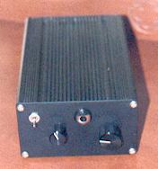
This was built for some one who wanted a cheap preamp, and headphone amp to start a system, it offers surprising performance. It was designed using the headphone amp as a basis.
For ideas on tweaking and more options and general info see the headphone amp Appendix & the Gallery
The Circuit
The circuit is very similar to the Headphone amplifier circuit. It is in fact an adaptation of that circuit.
The diagram below shows the basic circuit, not shown is the second stereo channel, input selector, recording output, also there is the option of using a switching headphone socket, to cut the output of the preamp when headphones are put into the socket.
There are several points of interest in the circuit. It uses a buffered input, followed by a low impedance volume control, this is a linear pot which has a logarithmic output, there is also a crossfeed section, this is only used for the headphone section of the circuit.
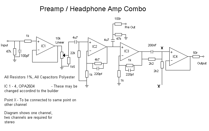
The Volume control in this circuit is buffered, this prevents the pot from placing any changing loads on the preceding stage making it hard to drive, and also consequently provides a constant high impedance input for the source. The pot used for the volume control is a linear type, a logarithmic one could be used, but the 1k5 resistor would have to be left out. The Linear pot in this application has several advantages, firstly it is easier to obtain a decent pot of this type that a log type. Secondly the tracking error of a linear pots is generally better. Lastly the output of this configuration is far more logarithmic, than a so called log pot.
The majority of the gain is made up in two stages the first being around IC2, the second around IC3. Between IC3 and IC4 is the crossfeed circuit, see diagram above.
In this project my version uses a mixed bunch of i.c's I have used OPA2604's in the input stage for IC1, IC2 and IC3. The IC4 uses LM6171 Opamps, I used these because of the high drive capabilities. I did originally use 5532's and 5534's. The change was definitely worth it. The OPA's have very low distortion, and the LM6171 is very fast amplifier with a wide band width.
Input Selector and Record Output
It is important to use a decent quality input selector, I used one by Lorlin, it has silver contacts, from their PT Rotary Range Datasheet. The Record output is simple taken from the common output of the switch to there socket.
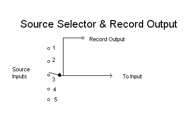
The diagram show an example of how the input selector could be implemented, the switch you use must have enough poles to switch the desired amount of sources. The switch should also be dual gang, the diagram shows only one channel of the selector this is obviously repeated for the other channel.
The final choice of input and switching selection will be left for the user to decide, one could include a tape loop for example.
Headphone Switching
The Preamp output of this circuit could easily be wired so that it is switched off when a headphone plug is placed in the headphone socket.
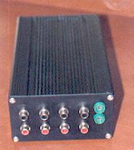
It is important to use decent quality sockets for all the inputs and outputs, phono sockets for the line out, record out and all the source inputs, and either 0.25" or 3.5mm Jacks for the headphones, Gold plated if possible.
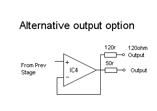
One could include a combination of sockets for either different size headphone plugs, and different impedance's, by incorporating the correct output resistor before the plug, taken from before the 50r resistor on the output of IC4. See Diagram Below.
Decent headphone sockets with switching outputs are easy to find, try to get one with gold plated contacts and a nice bezel. The switch can be used to mute the preamp output for headphone use. In which case you will need a double pole switch in the socket.
Crossfeed
More Info on crossfeed can be found here.
The Power Supply
The power supply used for this circuit is shown below, the power supply is exactly the same as the one used for the headphone amp. This will provide clean DC, with no hum what so ever.
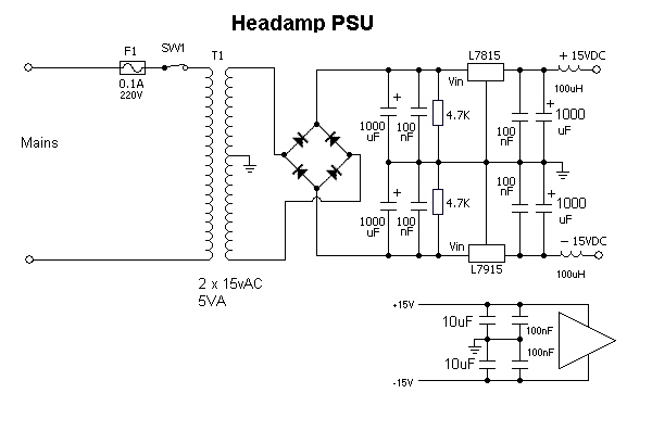
I have built an out board power supply for my equipment the is able to supply several units clean power at a variety of voltages from 5v to +- 15V upto 1Amp from each output. This is great and really handy. I don't get any hum problems due to the transformer being remotely locates out side the equipment case, I have excellent regulation due to being able to use a large toroidal transformer. This supply also has a rock steady output, which is essential in audio. The version I have built has a external transformer plug pack, and is rectified in the case, as above.
The Result
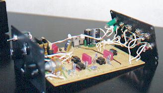
I was really pleased with the result of this, as a preamp it sounds great, it is clear and simple and the sound reflects this, as a headphone amp it also sounds great with plenty of drive. It takes no time to build and if laid out well on stripboard it will sound good, use decent components, this will help insure decent sound. This is now being used with great joy of the new owner daily.
Bibliography
During this project references were made to:
See Appendix to Headphone Amp for more details and options - Appendix & Gallery
Better Volume control, By Rod Elliot - ESP Website See Links Pages
Natural Crossfeed & Enhanced Bass Natural Crossfeed, By Jan Meier. More Info on crossfeed can be found here.
Several Datasheets found elsewhere on this site.
Site Disclaimer
Page Updated
06 October 2001