
Headphone Amplifier
The Headphone Amp - Appendix by Dan Ward
RS Components - Parts List
The parts list are in three 'sections'. Order 1 is the Power supply components, Order 2 is the Headphone amplifier components, Order 3 contains the parts I used for the case. Note, some components could only be ordered in packaged quantities, e.g. min 10 or 5 items so items could be over ordered, this can be minimized by carefully "merging" all three lists. I.e. Combining to make an overall parts list.
Below are the text files of the Parts list directly from the RS components CD-ROM catalogue (sept 2000 - feb 2001). Note. Part numbers may no longer be valid or valid at foreign RS components suppliers check Part Numbers carefully. List also contain some parts you may wish not to use, i.e. Power connectors?... These should be changed according to how you the user want need, require.
Headphone Amp - Parts List Download
The Part Numbers found in the lists can be used at the RS components Website, they have an online product catalogue that will show you exactly what I used. I would say at the time of publishing this list of parts 99% of the stock numbers were good.
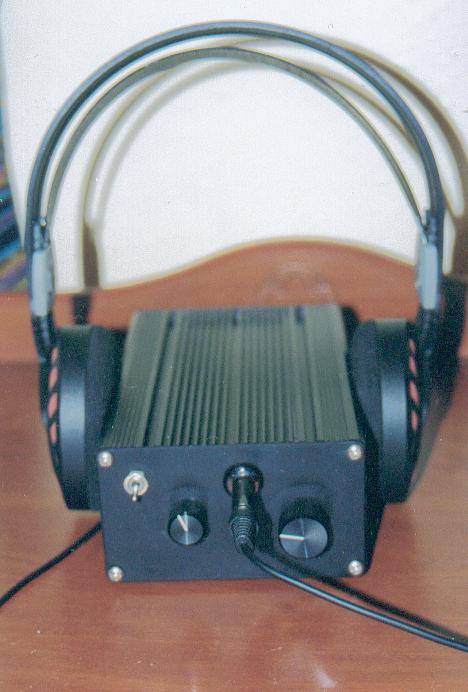
Case style, I used a "Heatsink"case, this is Matt black extrusion and matt black brushed front and rear finish and will easily accommodate a 100mm PCboard, with no mounting prep required. Just drill the faces and go. The Case can be seen in the Gallery
My Version, Biassed to Class-A
The version I use of this amp, is slightly different to the published version, the opamps have all been biased to class-a. By all accounts it is supposed to 'supposed to improve the sound of the opamps' but I am not sure.
It certainly did a few things, firstly increased the heat dissipation of the opamp considerably. Secondly, it did something to the sound, I would not say this is a bad quality, I enjoy the sound of the class-a version, it has got rid of some of the sterile sound typical of opamps, more correctly I should say the opamps do not sound as sterile as before. After longer test I have been completely convinced that this works great.
The mod was carried out by adding a resistor between one of the power rails and the output of the opamp, see diagram below. This is not recommended for dual opamps (really!). The size of the resistor determines the current flow, through one of the output transistors, which one depends on the type of the opamp, and the supply rail the resistor is attached to. I put half my bias resistors on one rail and half on the other supply rail. With one of the transistors always on passing current, the opamps is in class-a operation although only at low levels, were the signal is smaller than the bias current.
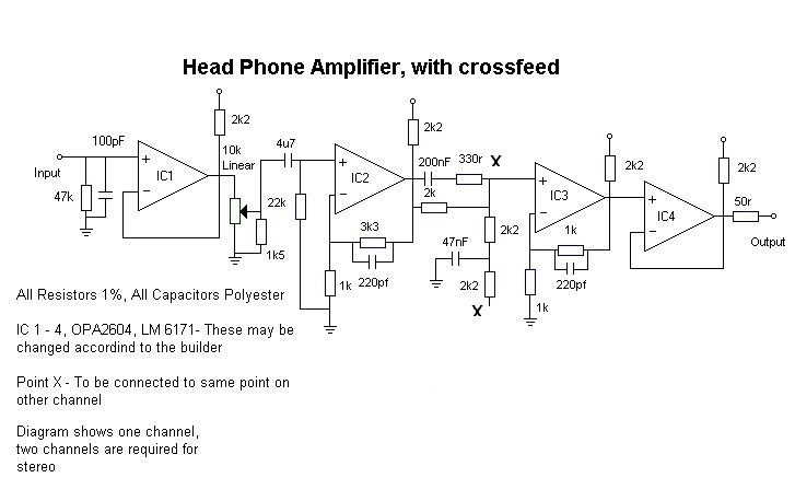
What current?? I used 2.2k resistors this gave me, I = V/R = 15 / 2.2k = 6.8mA, I used this value because it was handy! Experimentation is needed, here. Based on whether you like the sound, and how much the opamps can take do not exceed the max dissipation of the opamp, and consider using a heatsink. I would suggest not exceeding 10mA. Note if you have DC on the output of an opamp, in this circuit, it could damage your headphones, check circuits well. As this is likely to happen without care. For Heat sink ideas see the tips page.
It is important for this design to ensure that the power supply is as clean as possible, the power supply in the main project is fine. The main reason for the need to have a decent supply is that any noise on the supply can end up on the output through the bias resistors.
In some circuits you may get a problem with DC on the pot, this would be the sound of crackling or noise. In this case you may want to try the capacitor on the input to the pot, I did not have a problem so I just put, it as shown in the diagram, but I remain very suspicious as to why I did not need it!!!... Any comments welcome!?
You may want to consider using a capacitor on the output to stop any potential DC occurring on the output. This will reduce the risk of damaging your headphones, should the worst happen, I personally have not had a problem and have not bothered.
As more info on this becomes available, I will publish it here.
Switchable Crossfeed
For those not sure about crossfeed, as I was to start off with... It is very easy to make the crossfeed switchable. The important point to this is make sure that the quality of the switch is good, I would recommend using one from the Lorlin range, they have good quality silver contacts, and are suitable for this application. See Lorlin PT Datasheet. In this configuration, it makes it possible to use the crossfeed, or switch it off.
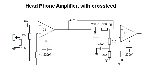
The switch is connected to by-pass the crossfeed circuit, between IC2 and IC3, remember thou this has to be carried out on both channels of the crossfeed circuit. The diagram is shown above. If desired a variable version of this circuit can be built, this would allow the listener to select, how much crossfeed, he or she may want to use according to their tastes, music, headphones. For more information about this check out the articles on crossfeed, for the appropriate values of components to use.
Further Revelations
Any further information for the headphone amplifier project will be published here, so before building, besure to check this page. For more pictures see Gallery
Bibliography
During this project references were made to:
Better Volume control, By Rod Elliot - ESP Website See Links Pages
Natural Crossfeed & Enhanced Bass Natural Crossfeed, By Jan Meier. More Info on crossfeed can be found here.
Several Datasheets found elsewhere on this site.
Site Disclaimer
Page Updated
06 October 2001