
Headphone Amplifier
The Headphone Amp by Dan Ward
Intro
I needed a headphone amplifier, for use in the tiny hours, and when noise was not an option. I had been meaning to build one for a long while. Wanting something that would sound good and on par with the rest of my system, that would be easy to build, I looked at several different ways of tackling the problem, and other peoples ideas.
I eventually decided on this op-amp based circuit, and built it last year. After many hours of modifications and tweaks I am now completely satisfied with the result, and my final design. The design uses opamps and parts which are easily available. I have slightly tweaked the design shown here into class-a, and done a couple of other things to improve the sound that is all revealed later on...
The problem with most systems, is if they do have a headphone socket, manufacturers rarely spend any time or money designing it. Consequently the sound quality reflects this, my design has done away with that problem completely.
After reading this you can find additional Info & Updates here - Appendix & Gallery
The Circuit
The Circuit is shown below, there are several points of interest in it. It uses a buffered input, followed by a low impedance volume control, this is a linear pot which has a logarithmic output, there is also a crossfeed section, to correct for the fact that these are not speakers...
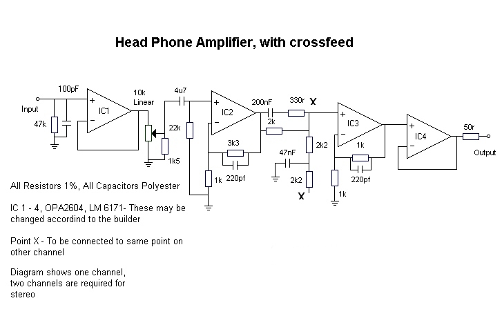
The Volume control in this circuit is buffered, this prevents the pot from placing any changing loads on the preceding stage making it hard to drive, and also consequently provides a constant high impedance input for the source. I also have not included any input capacitors because this helps minimizes low frequency attenuation , high frequency distortion. The pot used for the volume control is a linear type, a logarithmic one could be used, but the 1k5 resistor would have to be left out (not advised unless you want to buy a nice expensive pot.). The Linear pot in this application has several advantages, firstly it is easier to obtain a decent pot of this type than a log type. Secondly the tracking error of a linear pots is generally better. Lastly the output of this configuration is far more logarithmic, than a so called log pot. This setup works well and is easy to implement.
I had to include a capacitor after the pot this avoids the possibility of DC on the pot getting into the preceding stage, in event of a fault. The only other capacitor in the signal path is that of the crossfeed, this can however be switched out in event of it not being needed, even missed out completely. See further info later.
The majority of the gain is made up in two stages the first being around IC2, the second around IC3. Between these two IC's is the crossfeed circuit, see below. When opamps are used in a circuit it is better to generally keep the per stage gain down to a minimum, this helps preserve not only the life, by not stressing the IC, but also the sound quality, any gain stage that is pushed looses quality.
In this project my version uses a mixed bunch of i.c's I have used OPA2604's in the input stage for IC1, IC2. The IC3 and IC4 use LM6171 Opamps, I used these because of the high drive capabilities. I did originally use 5532's and 5534's. The change was definitely worth it. The OPA's have very low distortion, and are fast, and the LM6171 is very fast amplifier with a wide band width, low distortion and has high drive capability.
Crossfeed
The crossfeed circuit used in this design is an enhanced bass version of the original crossfeed circuit, and works by mimicking the mechanisms, the human brain uses to locate sound. The circuit used in this design was developed by Jan Meier. I shall now attempt a simple explanation of the circuit!!
If we consider the individual mechanisms, the speakers, the listeners head and room reflections.
The speaker, if you look at an individual speaker in a stereo setup, say for instance the right speaker. The sound produced by this speaker, will reach both ears of the listener, but apart from reaching the right ear, the sound is also heard by the left ear. The sound reaching the left ear, arrives slightly later and quieter than the sound reaching the right ear. Thus the sound reaching the left ear is attenuated and delayed.
The brain uses this attenuation and delay information to workout exactly were in a listening plain or any other plain a source is located. (Stereo Image)
The same happens for the left speaker in the setup but in reverse.
The Listeners head, your head acts a bit like a selective sponge, i.e. It absorbs some of the sound information that hits it and reflects other parts of it. Any sounds which the ear canal absorbs, have the possibility of been changed by the reflections from around the outside of the ear. So soundwaves which do enter into the ear canal, get either amplified or attenuated, this is frequency dependent, and not an exact science from one persons ear to the next (not all ears are the same, some are big some are small!). These reflections are also depended on the position of the persons head relative to the source. (i.e.. Standing on ones head! :-)
Room reflections, every room you setup a sound system in will cause the sound to be different, your living probably does not echo, but your town hall probably does. This is known as reverberation, it is sound waves which are bouncing of the room walls, furniture and curtains, etc. When they reverberate around the room they lose energy and obtain a delay by the extra distance they travel. This is what the brain uses to get a feel of the space around it. Lots of angles in a room, such as book cases, windows, drinks cabinets, and curtains or furniture all help to shape a sound. And make a room better to listen in.
After all that, to make things even more complicated! When you move your head, these are further refined, by slight changes in delay and attenuation of the signal.
So when you place a set of headphones on your head, the sound from each transducer only reaches the ear which it is coupled to. Thus it is easy to see that most of the above does not count anymore. No Reverb, Nearly No attenuation and delay.
We can say that the mean direction information can be obtained by the difference between the signals to left and the right ear. This is has been called the "natural" crossfeed, and will get rid of most of the above symptoms when listening with headphones. So a crossfeed from the right signal to the left signal, is obtained by the difference crossed to the other side, with some attenuation and delay.
This is represented by the mathematical formulae:
Vleft,out(t) = Vleft,in(t) + a .Vright,in(t-t0) a < 1
Vright,out(t) = Vright,in(t) + a .Vleft,in(t-t0)
(a being the frequency dependent parameter).
The time delay applied to the signal, is crucial, and should be approximately 300 ms.
More Info on crossfeed can be found here.
Headphone Switching
The output of this circuit could easily be wired so that it can be used with different impedance headphones. Some headphones sound better in a higher impedance socket.
It is important to use decent quality sockets for all the inputs and outputs, phono sockets for the line in, and either 0.25" or 3.5mm Jacks for the headphones, Gold plated if possible, although these may not "sound" any different the least they will do is not oxidize as quickly (if at all), as will standard jacks.
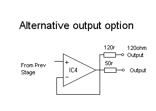
One could include a combination of sockets for either different size headphone plugs, and different impedance's, by incorporating the correct output resistor before the plug, taken from before the 50r resistor on the output of IC4. See Diagram Below. This is useful.
Decent headphone sockets are easy to find, try to get one with gold plated contacts and a nice bezel. Some have built in switches that may be used for a variety of things. The switch can be used to mute the preamp output for headphone use. In this case it is probably better not to use them, mute the speakers by either turning off your amp or preamp, most preamps do not require power to pick up a source in the record out. I have my headphone amp connected to the record output of my preamp, the switching in my preamp does not require any power so, I can used the source selector with power only on at the source and the headphone amp.
The Power Supply
The power supply used for this circuit is shown below, this will provide clean DC, with no hum what so ever. The circuit, has been tested with a really bad power supply, which I had lying around and still sounded excellent with no hum what so ever, this circuit is somewhat overkill.
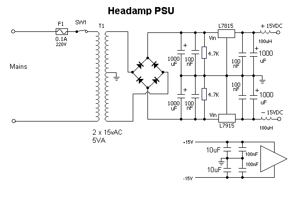
It has inductors on the output to minimize high frequency noise, and extensive decoupling and reservoir caps.
The Result
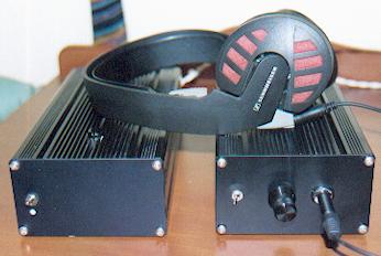
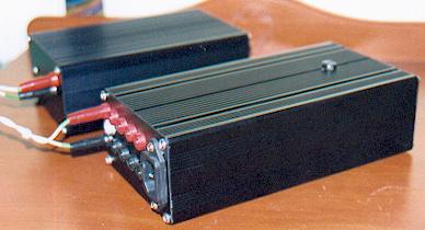
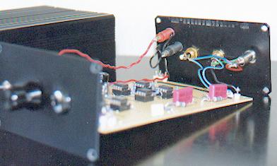
The result of this project was an awesome sounding amp, I have become addicted to headphones now.
The amp sounds clean and inviting to listen to, the bass is great but not overkill and the crossfeed helps compensate for the natural roll-off of the headphone transducers. Listening on my Sennheiser headphones is great. I spend a lot of time listening to this amp, my version is biased to class - A, but even before I did this it was excellent. The class-a option furthers on this taking me to pleasure.
I even got persuaded to build a modified version of this into a preamp / head-amp combo, for a friend. It reproduces what you put into it, I hate listening to bad recordings on this because, this reproduces everything so accurately that you put through it, it is a night mare. Use it with good recordings and you will love it.
See Appendix Additional Info, and Gallery for other photo's
Bibliography
During this project references were made to:
Better Volume control, By Rod Elliot - ESP Website See Links Pages
Natural Crossfeed & Enhanced Bass Natural Crossfeed, By Jan Meier. More Info on crossfeed can be found here.
Several Datasheets found elsewhere on this site.
Site Disclaimer
Page Updated
06 October 2001