
Natural Crossfeed
Natural Crossfeed - By Jan Meier, Editted By Dan Ward.
For me, listening to music is a very private affair. Throughout my life, my musical tastes always have been somewhat different from that of the other people I lived with. Consequently, I learned to appreciate good quality "cans." This appreciation has increased since, as a teenager and as a student, I never had the financial means to buy loudspeakers that could stand up to the sound quality offered by my Sennheiser and Beyerdynamic headphones.
Nonetheless, listening was not all heaven on earth. The in-head localization phenomenon did not please me. With recordings presenting a wide soundstage, some instruments are heard in one of the two audio channels only. This is most annoying, like a bee buzzing in one's ear.
Some 15 years ago I experimented with electronic crossfeed by bridging the left and right outputs of the headphone channel of my amplifier with resistors. Although the crossfeed thus produced cured the "buzzing bees," the sound became extremely dry and I dropped the idea.
In the last few years, a number of systems have appeared on the hi-fi market that also produce crossfeed, but in a much more refined way. The analogue headphone amplifiers of HeadRoom and the digital systems of Sony (VIP 1000), Sennheiser (Lucas), and AKG (Hearo 777) are well-known examples. These systems all more-or-less cure the problem of the in-head localization experienced with headphones.
These systems work by simulating the mechanisms that a person uses to locate and externalize sources of sound:
First, the sound of a source to the right side of the listener (e.g., the right loudspeaker in a stereo setup) not only reaches the right ear, but attenuated and delayed, is also heard by the left ear. The level of attenuation and the delay time of this crossfeed signal provide important directional information.
Second, the soundwaves are partly absorbed and partly reflected by the listener's head. Especially, the reflections at the ear pinnae interfere with the soundwaves that directly enter the ear canal and amplify or attenuate specific frequency components. As these reflections depend on the direction of the soundwave, the "color" of the sound changes with the direction of the source.
Third, reflections of soundwaves on the walls of the listening room produce reverberation that conveys an extra feeling of space.
The information obtained by these mechanisms is further refined by movements of the head. Changes in sound levels, delay times and sound color refine our sense of direction. For a demonstration blindfold a friend and ask him to locate a ticking clock that you have hidden in the room. He will start turning his head, although he can't see it. With his head in a fixed position, he will find an exact localization much more difficult.
All these mechanisms are missing when we hear music using headphones. The transducers are directly coupled to our ears. The sound of the right (left) transducer will not reach the left (right) ear and the reflections on the oracles have changed and hardly interfere with the original soundwave. Moreover, the sound-sources are attached to our head, so head movements no longer add information. Reverberation is not present.
In principle, digital sound processors can simulate the mechanisms described, but the results are, thus far, not fully satisfactory, because the reflections on the pinnae are very complex and listener-specific.
Fortunately, the mean directional information is provided by the differences between what we hear by our two ears. A "natural" crossfeed from the right (left) audio signal to the left (right) transducer, with an appropriate attenuation and delay, will reduce most of the adverse symptoms of headphone listening considerably.
A straightforward approach to mimic crossfeed is to take the original stereo signal, attenuate its amplitude and have it delayed. Then cross the two channels and add the processed signals to the original stereo signal. In a mathematical formula:
Vleft,out(t) = Vleft,in(t) + a .Vright,in(t-t0) a < 1
Vright,out(t) = Vright,in(t) + a .Vleft,in(t-t0)
The HeadRoom systems work like that (with a being a frequency dependent parameter). For a more detailed information just take a look at their most enjoyable homepage (http://www.headphone.com). The people at HeadRoom are very fine engineers, but have not revealed the schematics of their circuitry. So when I decided to build my own headphone-amplifier, I had to design an appropriate crossfeed-filter myself.
The crucial part in the crossfeed-filter is the realization of the required time delay of approximately 300 ms. Although standard solutions for signal delay can be found in many text books on electronics, a fixed frequency-independent delay with headphones has one major drawback: the so-called Comb-effect.
A conventional crossfeed filter, such as that realized by HeadRoom, mimics the sound of a left or a right sound source most adequately, but the frequency-spectrum of a source in front of the listener is unnecessarily disturbed. For this in-front source, the left and right audio signals are equal: a mono signal. In principle, these signals need no crossfeed. However, with conventional solutions, there still is, and the audio signals at the headphone-transducers become:
Vleft,out(t) = Vright,out(t) = Vleft,in(t) + a .Vleft,in(t-t0) a < 1
Especially in the high frequency range, the delayed crossfeed signal interferes with the original input and attenuates specific frequencies. The frequency-curve is no longer flat but shows a larger number of dips (the Comb-filter effect). HeadRoom compensates for the overall attenuation with a filter that gently lifts the higher frequencies, but the dips in the frequency-curve do not disappear.
With a fixed delay, the Comb effect can not be eliminated, so I decided to make the delay of my crossfeed filter frequency dependent. For localization of a sound source, the delays of the frequencies below 2 kHz are the most important, and therefore should have a natural 300 ms delay. For higher frequencies the delay is reduced. Moreover, by also slightly shifting the original audio signals in the other direction and by giving them a small, frequency dependent attenuation before the crossover signals are added, the mono signals will be left undisturbed! A music signal that simultaneously is found on both channels is left unchanged, and a signal on only one input channel is partly transferred to the other channel, with an appropriate time delay at low frequencies.
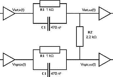
Figure 1
Take a look at the basic crossfeed circuit shown in figure 1. The crossfeed is performed by only three resistors and two capacitors! It's hard to believe, but the circuit really does the job!
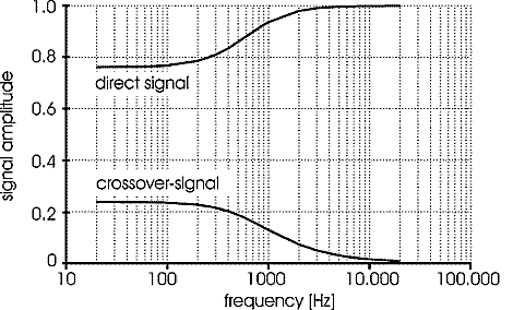
Figure 2
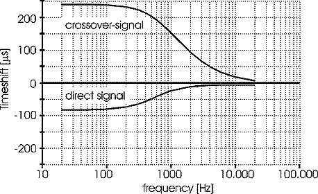
Figure 3
For those interested in the technical details, figures 2 and 3 show the
amplitudes and the time delays of both the crossfeed-signal as well as
the (direct) audio signal. The amplitude of the crossfeed-signal decreases
with frequency, and thus mimics the shadowing effect of the head at higher
frequencies. In the lower frequency-range, the time delay between the
crossfeed and the direct signals is 320 ms, and thus mimics the natural
delay for a loudspeaker seen at an angle of approximately 30 degree by
the listener. By choosing different parameter values for resistances and
capacities the crossover signal can be "tuned", but with the
values shown it works well for my ears with 95% of all my recordings.
SOME MATHEMATICAL STUFF
With a conventional crossfeed filter, the direct signal equals the original input signal, and the crossfeed signal is realized by attenuation and delay:
Vinput(t) = cos(2pft)
Vdirect = Vinput(t) = cos(2pft)
Vcrossover = a(f).cos(2pf(t-tdelay))
a(f) << 1
With a mono signal, both direct signals are equal and both crossfeed signals are equal. The output signals become:
Vout(t) = Vdirect + Vcrossover = Vinput(t) + a(f).cos(2pf(t-tdelay))
The second term interferes with the input/direct signal and results in a number of dips in the frequency spectrum at those frequencies where: 2pftdelay = (2n+1)p. This is the so-called Comb-effect.
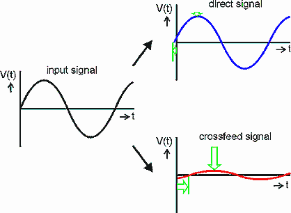
Figure 4
With the "natural crossfeed" filter, the crossfeed signal is
also realized by attenuation and delay, but now the direct signal is also
(slightly) attenuated and slightly time-shifted in the other direction
(figure 4):
Vinput(t) = cos(2pft)
Vdirect = A(f).cos(2pf(t+tdirect))
Vcrossover = a(f).cos(2pf(t-tdelay))
A(f) = sin(2pftdelay)/(sin(2pf(tdirect+tdelay)) » < 1
a(f) = sin(2pftdirect)/(sin(2pf(tdirect+tdelay)) << 1
tdirect << tdelay
2pf(tdirect+tdelay) < p/2
(This last condition guarantees that a(f) and A(f) will change monotonically with the frequency.)
The result is that, with a mono signal, the sum of the direct and the crossfeed signals equals the original input signal and there is no Comb-effect:
Vout(t) = A(f) cos(2pf(t+tdirect)) + a(f).cos(2pf(t-tdelay)) = cos(2pft) = Vin(t)
The condition 2pf(tdirect+tdelay) < p/2 requires that the effective delay (tdirect+tdelay) be shortened for higher frequencies. Natural delay times of 300 ms only can be realized for lower frequencies.
THE NATURAL CROSSFEED NETWORK
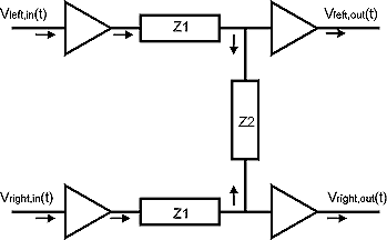
Figure 5
The basic network is shown in the figure 5. It contains a chain of three
passive networks, of which the outer two have the same impedance value.
It easily can be shown that:
Vleft,out(t) = (Z1 + Z2)/(2*Z1 + Z2) * Vleft,in(t) + Z1/(2*Z1 + Z2) * Vright,in(t)
Vright,out(t) = (Z1 + Z2)/(2*Z1 + Z2) * Vright,in(t) + Z1/(2*Z1 + Z2) * Vleft,in(t)
The crossfeed signals are given by the last terms of these two equations.
Using
Z1 = R1 // C1 = R1 /(1+iwR1C1)
Z2 = R2
the transfer function of the crossover becomes:
Z1/(2*Z1 + Z2) = (R1/(2*R1 + R2))/(1+iwC1R1R2/(2R1 + R2))
This is the transfer function of a first order low-pass Bessel filter with a filter frequency of:
f = (2R1 + R2)/(2pC1R1R2)
Using:
R1 = 1000 Ohm
C1 = 470 nF
R2 = 2200 Ohm
the filter frequency becomes f = 650 Hz.
To derive the time delay of the crossover signal:
f (phase shift of the transformation) = arctan(wC1R1R2/(2R1 + R2)) and
t (time shift) = f/(2pf) = f/w
For low frequencies:
f = wC1R1R2/(2R1 + R2)
t(w~0) = C1R1R2/(2R1 + R2)
For high frequencies:
f = p/2
t = 1/4f
To derive the time shift of the direct signal:
Amplitude A(f) = 1 - Z1/(2Z1+Z2) = (R1+R2+iwC1R1R2)/((1+iwC1R1R2/(2R1+R2))
f = arctan (wC2R1R2/(R1+R2)) - arctan (wC2R1R2/(2R1+R2))
t = f/w
t(w~0) = C1 R1 R2 / ( R1 + R2 ) - C1 R1 R2 / ( 2 R1 + R2 )
The two filter frequencies are:
f1 = 1/((2R1+R2)(2pC1R1R2) = f
f2 = 1/((R1+R2)(2pC1R1R2)
Using the crossover frequency instead, the time delay at low frequencies is 1/(2pf) = 250 ms. Together with a time shift of 70 ms of the direct signal, the effective time delay is 320 ms.
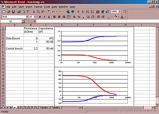
Download circuit simulation spreadsheet (in MS Excel format)
The MS-Excel circuit simulator (above) lets you experiment with the filter's component values for the standard crossfeed filter (see my article here for a simulator for my enhanced-bass filter). Component values can be changed in the upper left corner of the table. The pictures (the frequency response and time delay characteristics of the crossfeed filter) automatically adapt. The central branch in the spreadsheet consists of a resistor and a capacitor in series. For the standard version of the crossfeed filter, the capacitance has to be given a very high value so as to act as a short-circuit. Each side-branch has a parallel pair of a resistor and a capacitor in series. Each side branch thus consists of two resistors and two capacitors.
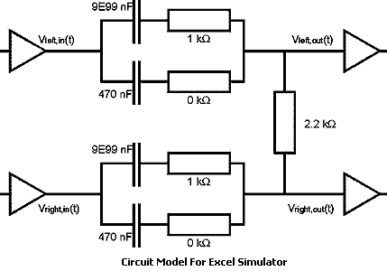
For the standard version of the crossfeed, one resistance has to be set to zero and its corresponding capacitance to the regular value (440nF / 320nF / 220nF). The other resistance has the regular crossfeed value (1.1k / 1.5k / 2.2 kOhm) and its corresponding capacitance is set to a very high value. The values in the spreadsheet are for a relatively low crossfeed level.
Natural Crossfeed & Enhanced Bass Natural Crossfeed, By Jan Meier