
60 Watt Power Amplifier
60 Watt Power Amplifier by Dan Ward
Intro
Transistor Based Power amplifier. Please Note - This page is incomplete.
This amplifier is a fairly simple design, it uses the common widely available 2N3055 Power transistor on the output, and a differential pair on the input with a class-A driver VAS stage. This amplifier was originally a kit.
The Circuit
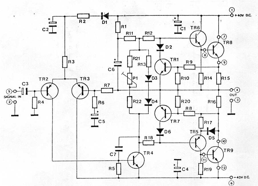
There are a few modifications you can do to this amp, for starters you could remove the input capacitor, but be warned only do this if you are sure pre-amp or driving stage, is protected from DC at it's output. You could also increase or match the input impedance. I increased the values of the supply rail decoupling capacitors as well and improved them by wiring some 100nf caps in parallel.
Input and Output Connectors
Make sure when you build an amp you use appropriate heavy duty output connectors. I.e. 4mm Banana plugs preferably gold plated, and decent input phono connectors. Althou gold plated connectors may not improve the sound quality they have the advantage that they do not oxidize.
Other Options
The Bias current used for this amplifier is not over critical, I used 120mA. I would recommend between 65mA and 90mA.
The amplifier operates in Class-AB, setting the bias current higher, will make the amplifier operate in Class-A for longer before operating in Class-B. The downside of operating an amplifier with high Quiescent current is that, it causes the output transistors to have to dissipate more heat, which means the amp will require more heatsink, this can add to expense.
Setting the bias current can be done in two ways the first is to connect an ammeter in series with the positive supply rail, and measure the current, allow the amplifier to warm up first this will help prevent variations in bias current. Allow the amplifier to stand for at least another half hour and check it again.
The second way is to measure the DC potential across the output resistors, this it then as before checked after 10 minutes and again after half an hour till the biasing is stable. I.e. 90mA = V/R = 27mV / 0.3R, so for 90mA bias current you would be looking to measure as close to 27mV as possible.
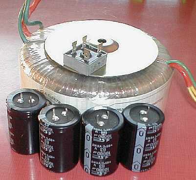
The Power Supply
I have not yet got round to Drawing a PSU diagram for this but I am just using a standard power supply with very similar components to those shown in this photo.
The Result
Having built this amp, and using it for about 7 months now. I can say it is a good performer, although it is not the best sounding amp I ever built, it is not to be ashamed of, and with a few mods here and there and a bit of tinkering, it has helped improve the sound quite a bit. This could also depend how you want to spend your money I know some "Audiophile!" types spend stupid money on ridiculous upgrades when they would be better of using the money to buy a better amp!
Anyway this is more for interest than anything else. Have fun.
Bibliography
During this project references were made to:
"Design with Discrete Transistors" by Douglas Self, D. Self - Website.
Several Datasheets found elsewhere on this site.
Site Disclaimer
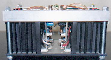
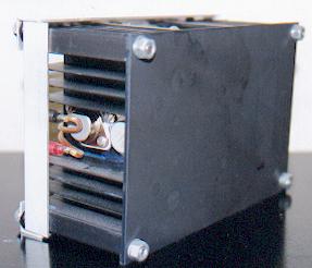
Simple and effective case even thought it is not fully shielded works well.
Page Updated
07 October 2001