
Line Driver & Line Receiver
Line Driver and Line Receiver by Dan Ward
Intro
Balanced inputs and outputs are used mainly for professional audio and "High-End" HiFi, for example on many CD players and DACs, it has been used in professional audio for many years.
A conventional HiFi interconnect uses coax cable with the center conductor carrying the signal and the shield providing the return as well. This is great in most situations, but in more demanding situations with long interconnects, they can pick up noise. This is because the inherent weakness of unbalanced interconnections is that the shield, which is also a signal conductor, is a path for power line related currents that always flow between equipment grounds. The voltage drop across the resistance of the shield and connectors adds directly to the signal, producing the familiar hum and buzz. This is not the only reason but is one of the many.
A balanced connection uses three conductors, two for the signal the twisted pair, and the third, for the shield, the two conductors in the center are twisted pair, one carries the non-inverting signal and the other carries the inverted signal, exactly the same but inverted. Any noise picked up by the cable will be equal on both the signal conductors, thus noise at the other end in the receiver gets canceled out be the differential configuration of the receiver amp.
This circuit would be good for connecting your hifi and PC, I am going to use it for this, as I have a 7 m cable run! It could also be used in situations, where the interconnects pick-up excessive noise.
The Circuits in this page are preliminary circuits, they are based solely on the Datasheets, with the odd exception. I am still investigating this subject as my back ground knowledge on this subject is no deep, but I have found some good sources of info, see bibliography.
The Circuit
The circuit is very similar to the Datasheet's circuit. It only also includes a buffer for the Driver, as the circuit datasheet states it should be driven with a low impedance source.
The diagram below shows the basic circuit, not shown is the second stereo channel, or the power supply.
The points of interest in the circuit, is the buffered input, it says in the datasheet that this circuit should be driven by a low impedance source, the buffered input provides this. Providing the ideal source, regardless of the input.
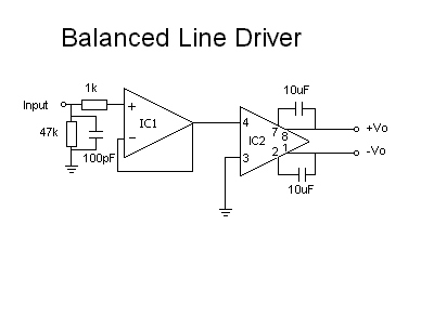
I think the op-amp selection is quite important for this project because the performance of the Driver will depend on the efficiency of the buffer, low-distortion is a prime importance. The DRV134 and the INA134 both have very low distortion, and SSM2141/2 combination has good distortion performance as well but not quite as good as the DRV/INA134 combo, although this is marginal.
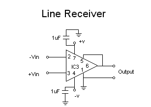
In this project use. IC1 I would suggest something like the OPA2604's or OPA604, you could use one dual op-amp for the buffers. IC2 uses either the DRV134 or the SSM2142 for the driver. The Receiver IC's, IC3 will be either the INA134 or the SSM 2141. The Datasheets for these IC's can be found else were on this site, in the Articles Section, these devices are interchangeable, The 134's are from Burr-Brown and the SSM's are from Analogue Devices.
Input and Output Connectors
The Input connectors to the driver and the output of the receiver can be normal phono connectors, if in a box, if built into a preamp, they can be hardwired to the preamp PCB inputs. The output of the driver and the input of the receiver, should be something like an XLR plug, as used by pro's, or a multi pin Din connector, althou these are not as high quality or provide by far a decent connection compared to the XLR.
Another alternative is the hard wire two boxes with the correct cable length between them, this would not only be cheaper but may even be more efficient, as there are not discontinuities between the shield, and the PCBs. With the correct mounting in an aluminum shielded enclosure this could work well.
The cable between the transmitter and receiver should be high quality twisted pair cable, balanced microphone cable is good, or proper audio twisted pair such as Belden 8451 or 9452. The quality is important, the tighter the twisted the cables are the better, also the type of screening can make a big difference. The best type of screening is probably, braided screen or over lapping foil screen, these types open up less on bends.
Other Options
One could design this line driver / receiver to be incorporatied into a complete "Computer Pre-amp". This could consist of a basic pre-amp circuit, which includes volume, line driver out, maybe two line inputs plus the computer, a record out for connection to a mini disk or something. You could include a cheap amp with some decent IC amplifiers, what about an active crossover similar to that of ESP pages? (See links section to find this project at RODE's site, ESP.)
The Power Supply
The power supply used for this circuit is shown below, the power supply is exactly the same as the one used for the headphone amp. This will provide clean DC, with no hum what so ever.
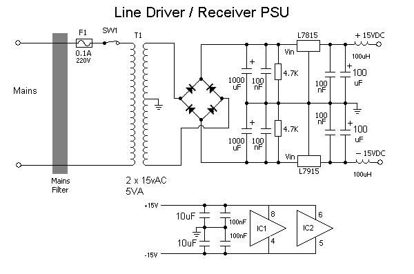
I would suggest you try using a power pack with decoupling and seperate regulators in the unit. This would work out cheaper.
I have built an out board power supply for my equipment the is able to supply several units clean power at a variety of voltages from 5v to +- 15V upto 1Amp from each output. This is great and really handy. I don't get any hum problems due to the transformer being remotely locates out side the equipment case, I have excellent regulation due to being able to use a large toriodal transformer.
Definitions
An UNBALANCED input or output connects one of its signal conductors to ground and has a non-zero impedance at the other signal conductor.
A BALANCED input or output uses two signal conductors which have equal impedance's to ground.
The Result
When I have built this circuit I will let you know how it performs. I should imagine this circuit will work as intended, in regards to performance, electrically it is guaranteed to work.
Bibliography
During this project references were made to:
"Balanced Line Driver & Receiver" by Rod Elliot, Elliot Sound Products.
"Balanced Line Technology " by Douglas Self, D. Self - Website.
Jensen AN-003 "INTERCONNECTION OF BALANCED AND UNBALANCED EQUIPMENT" - by Bill Whitlock
Several Datasheets found elsewhere on this site.
Site Disclaimer
Page Updated
05 Octobr 2001